Using VIO to Augment Robot Odometry
Overview
This tutorial highlights how to setup Visual-Inerial Odometry (VIO) into a Nav2 and ROS 2 based robotics system to augment robot odometry.
Many modern robotics platforms have unideal configurations for high quality wheel odometry. For example, skid-steer, tracked, omnidirectional robots using mecanum wheels, and legged robots are notorious for producing suboptimal odometry. These types of platforms are becoming increasingly common in the robotics landscape and require augmentations or replacement sources of odometry. Further, some applications of robotics technologies involve retrofitting existing equipment which may not have odometry altogether.
A subfield of computer vision and robotics focuses on how to use Visual (e.g. camera) and Inertial (e.g. IMU) data in order to compute high-speed relative motion independent of robot mechanics. This is an especially useful technology for UAVs without accurate intrinsic odometric sensing capabilities – or mobile robots with poor interinsic odometry measurements.
Thus, this tutorial walks through the integration of VIO into a robot system to replace or augment wheel odometry so that your robot can autonomously navigate with quality state estimation required for a well-engineered system that is able to accurately and predictably complete its tasks.
Throughout this tutorial, we will be using the Stereolabs SDK’s Position Tracking capability as our VIO solution of choice paired with the new ZED X camera. This VIO solution is easy to use and provides production-quality performance for free when using a ZED camera module.
Note
While we use the Stereolabs SDK and ZED X camera, this tutorial may be broadly used with other solutions. However, we recommend this option as an optimized solution that is tightly-coupling to the camera hardware and Jetson compute architecture for high performance and fast out-of-the-box results. It is Open Navigation’s experience that it can take months of testing of open-source VIO solutions and attempting to fix time synchronization issues with Stereo camera ROS drivers to achieve results of practical quality. This is very conveniently a one stop shop integrated solution.
Setting Up the ZED X Camera
We’re using the ZED X for the purposes of this tutorial due to its:
Smaller size similar to other AMR depth sensors
High quality depth information at relevent ranges for mobile robotics and manipulation
Hardware synchronized IMU
Wide field of view requiring only one camera in most situations
Use of GMSL2 connectors over USB (yay!)
Global shutter cameras for improved quality and removed motion blur
Though, any other ZED camera with an IMU in it will work as well (ZED2, ZED2i, ZED mini, etc). If you are using the ZED X in particular, checkout this playlist on YouTube showing step by step how to setup the Nvidia Jetson and ZED X for ROS 2 or ZED X Getting Started page to install the SDK, ZED X drivers, and ROS 2 drivers needed to proceed.
At this point, you should be able to run one of the following commands to launch the driver and visualize the sensor data in Rviz. Note that these are ROS 2 component nodes that also may be loaded into your system’s component manager to minimize latency due to serialization.
$ ros2 launch zed_wrapper zedx.launch.py
$ ros2 launch zed_wrapper zedxm.launch.py
As of September 2023, the driver out of the box produces the full map->odom->base_link->camera tree on its own. This is since the Pose SDK can produce not only VIO, but loop-closure VSLAM representing the full state estimation TF tree.
We want to be able to fuse in other information such as an external IMU, wheel odometry, GPS, or other sensors into our local or global state estimates, so we need to disable TF publication of map->odom and odom->base_link to be provided by our fused outputs. Especially considering the ZED X camera knows nothing about the nature of the base_link frame. However, if you would like to use the ZED’s state estimate for your entire system without further sensor fusion, you certainly can!
Setting Up ZED ROS
In order to run VIO alone, we need to do the following:
Stop computing VSLAM’s
map->odom, TF transform. This part of the TF tree is provided by our global localization solution (e.g. AMCL, GPS, fused global state estimate).Disable VIO’s publication of
odom->cameraand instead publishnav_msgs/Odometryof the VIO’s pose solution for fusion. By default thezed_wrapperpublishes this under theodomtopic, but it is recommended to remap this to a non-reserved topic name (for example,camera_odom).Re-configure the ZED Wrapper’s parameters to obtain the best VIO as possible.
two_d_modewill force the pose tracking to be in 2D dimensions (e.g. X, Y, Yaw) for indoor or 2D applications.pos_tracking_enabledwill disable or enable pose tracking, if you desire it (and we do here!).path_max_countwill set the maximum size of the visualization of the pose over time. By default it is infinite. We should make this finite.qos_depthwill set the QoS depth throughout the driver. Set this to 3-5 for all options. 1 may result in dropping of messages in very temporary blibs in compute. 3-5 allows us to buffer a small handful of measurements to process for very short term blibs, but clears them all the same in CPU thrashing situations.
Thus, make the following parameter updates to the zed_wrapper’s default parameters:
pos_tracking:
    publish_tf: false # Disables odom -> base_link TF transformation
    publish_map_tf: true # Disables map -> odom TF transformation
    area_memory: false # Disables loop closure computation, but Pose topic for global VSLAM still published (but now pure VIO)

    # Optional optimizations
    two_d_mode: false # Or true, up to you!
    pos_tracking_enabled: true # of course!
    path_max_count: 30
    qos_depth: 5
Optionally, remap the zed odom topic to a topic that isn’t reserved or commonly used by other systems. In your ZED launch file add to the node / launch file:
remappings=[('odom', 'camera_odom')]
Note
The ZED driver will publish two pose tracking topics, pose and odom. Pose is the full V-SLAM pose with loop closures (or not, if area_memory: false). The odom topic contains the actual VIO that we’d like to use, which publishes at frame capture rate. The Pose topic may publish at irregular frequencies depending on loop-closures. Thus, we’d like to use odom for this local fusion.
Fusing VIO Into Local State Estimate
Now that we have the ZED ROS 2 drivers set up to publish our VIO to a topic and leave our TF tree to the fusion algorithm and Robot State Publisher (e.g. URDF), we’re finally ready to fuse in VIO into our broader state estimate using the robot_localization package.
This package is a generalized EKF and UKF solution to state estimation of potentially many different topics, publishing at different rates, of different types. If you’re unfamiliar with robot_localization checkout our First-Time Robot Setup Guide’s Odometry page for basic information and the package’s extensive documentation.
Most users at this point already have a robot_localization configuration file in their robot systems to fuse existing sensors together, such as wheel odometry (even poor) and robot IMUs. We’ll be adding a new odom field, odom1, to our configuration to fuse in VIO’s position and orientation into our filter. If this is your first odometry field, use odom0 and you can base your file on ekf.yaml.
odom1: camera_odom # Adjust if namespacing ZED camera (e.g. /zed/odom)
odom1_config: [true,  true,  true,  # X, Y, Z
               true,  true,  true,  # Roll, Pitch, Yaw
               false, false, false, # Vx, Vy, Vz
               false, false, false,  # Vroll, Vpitch, Vyaw
               false, false, false] # Ax, Ay, Az
odom1_differential: false
odom1_relative: true
odom1_queue_size: 2
Note
We’re fusing in Roll, Pitch, and Yaw. If operating your EKF or ZED in 2D modes, then set the Roll and Pitch fields to false. If you believe jumps in your VIO may occur, consider using odom1_pose_rejection_threshold which sets a threshold to reject updates if sufficiently outlandish relative to recent updates. In this case, setting differential to true may also be helpful so that single bogus updates don’t move the entire coordinate system.
Make sure to evaluate your EKF’s frequency, two_d_mode, publish_tf, and key frames to be appropriate for your application. We generally want to publish TF and have 2D mode on when navigating in flat indoor environments only.
Fusing VSLAM Into Global State Estimate
While out of the scope of this tutorial, it is possible to continue to produce VSLAM results for global localization with loop closure (both in general and using the Stereolabs Position Tracking SDK). The steps for integration are similar to the last sections, except:
Continue to disable the TF tree for
map->odom, but the global pose topic will continue to publish underposefor fusionFuse that topic into a global localization EKF in
world_frame: mapalong with other sources of information (e.g. external IMU, AMCL, GPS, etc).The fusion of multiple global localization techniques should be done carefully. The most trusted source should be set
_differential: falseto use the actual pose information. All other subsiquent systems should use_differential: trueso that diverging coordinate systems do not create bouncing solutions. Instead, this will fuse one as absolute poses and the other as the changes of poses between iterations.
Testing it Out!
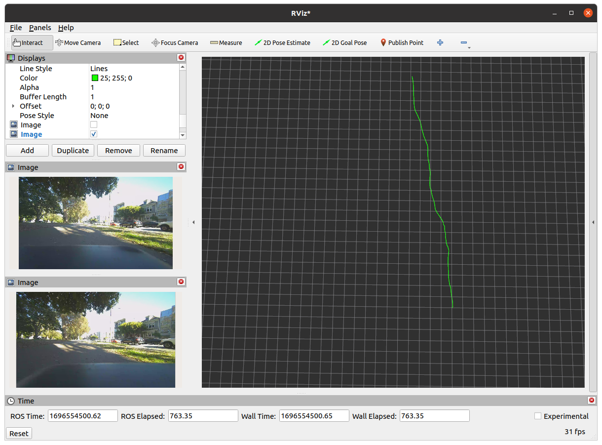
In the below example, we’re fusing the Stereolabs SDK’s Pose Tracking VIO solution with a robot’s external IMU and odometry (e.g. robot_localization has odom0 odom1 and imu0) to improve performance while navigating on a legged robot platform in outdoor environments. The robot’s internal odometry based on leg motion is quite poor and causes the robot to have generally poor autonomous navigation performance.
The Visual-Inertial Odometry’s error over these datasets is 4.1% over the 70m path. Typically for ‘good’ odometry from wheel encoders + IMU, I would like to see 2-3% fully tuned (or less than 1% for ‘great’ odometry), so this is a great source! Fused in with the legged robot odometry, it improves overall performance to an acceptable level!
Note
Steve is walking his robot dog through Golden Gate Park in San Francisco, CA with a joystick to collect this data. Steve’s a bad robot driver (he doesn’t play video games), the zig-zagging you see is due to his lack of good joystick control + the quadruped has alot of additional assymmetric weight on it. It is not representative of Nav2 and should be mocked. Its meant to test the accuracy of the VIO solution in more harsh conditions… yeah… lets go with that.