Using Collision Monitor
Overview
This tutorial shows how to use a Collision Monitor with Nav2 stack. Based on this tutorial, you can setup it for your environment and needs.
Requirements
It is assumed ROS2 and Nav2 dependent packages are installed or built locally. Please make sure that Nav2 project is also built locally as it was made in Build and Install.
Configuring Collision Monitor
The Collision Monitor node has its own collision_monitor_node.launch.py launch-file and preset parameters in the collision_monitor_params.yaml file for demonstration, though its trivial to add this to Nav2’s main launch file if being used in practice.
For the demonstration, two shapes will be created - an inner stop and a larger slowdown bounding boxes placed in the front of the robot:
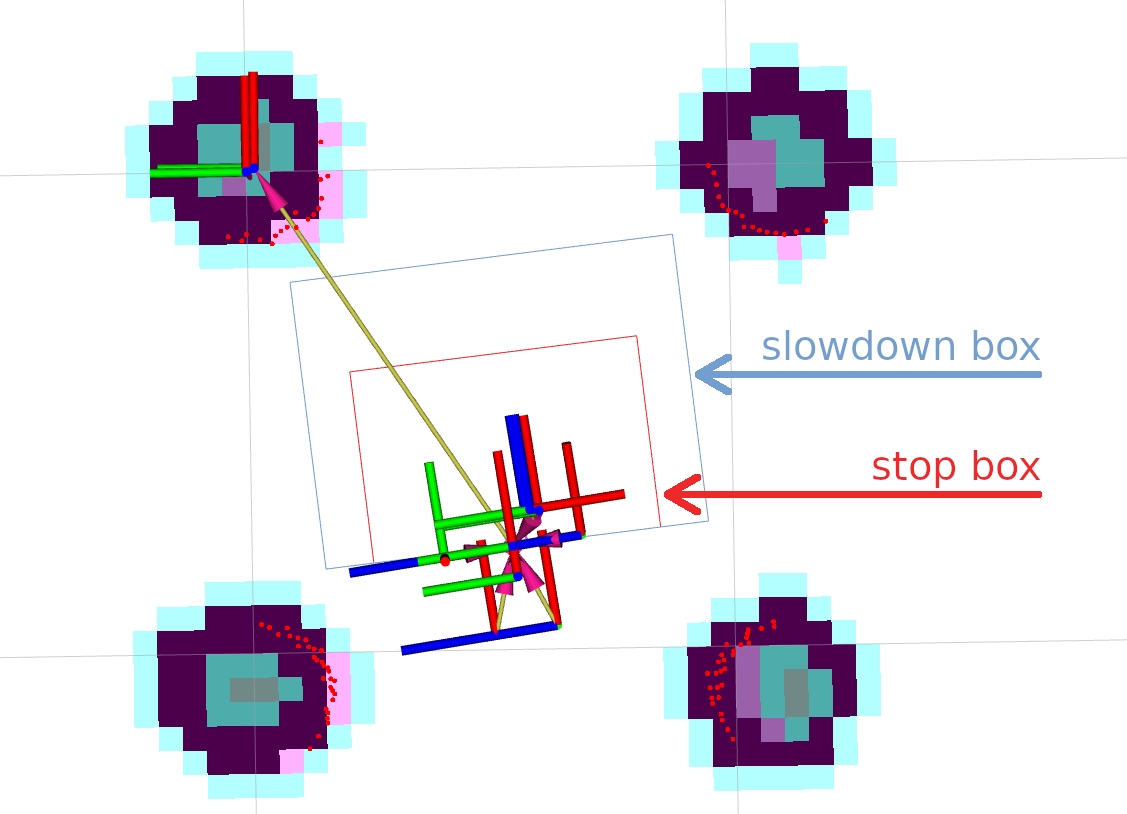
If more than 3 points will appear inside a slowdown box, the robot will decrease its speed to 30% from its value.
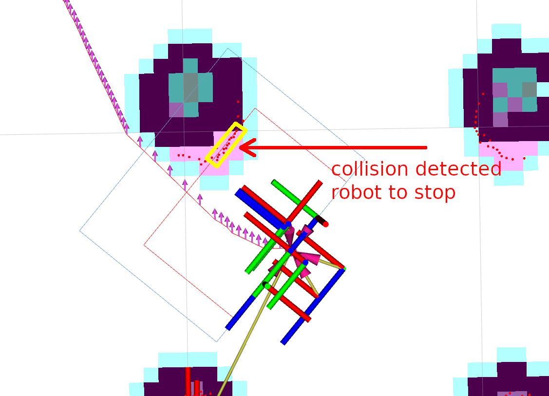
For the cases when obstacles are dangerously close to the robot, inner stop zone will work.
For this setup, the following lines should be added into collision_monitor_params.yaml parameters file. Stop box is named as PolygonStop and slowdown bounding box - as PolygonSlow:
polygons: ["PolygonStop", "PolygonSlow"]
PolygonStop:
  type: "polygon"
  points: "[[0.4, 0.3], [0.4, -0.3], [0.0, -0.3], [0.0, 0.3]]"
  action_type: "stop"
  min_points: 4  # max_points: 3 for Humble
  visualize: True
  polygon_pub_topic: "polygon_stop"
PolygonSlow:
  type: "polygon"
  points: "[[0.6, 0.4], [0.6, -0.4], [0.0, -0.4], [0.0, 0.4]]"
  action_type: "slowdown"
  min_points: 4  # max_points: 3 for Humble
  slowdown_ratio: 0.3
  visualize: True
  polygon_pub_topic: "polygon_slowdown"
Note
The circle shape could be used instead of polygon, e.g. for the case of omni-directional robots where the collision can occur from any direction. However, for the tutorial needs, let’s focus our view on polygons. For the same reason, we leave out of scope the Approach model. Both of these cases could be easily enabled by referencing to the Collision Monitor configuration guide.
Note
Both polygon shapes in the tutorial were set statically. However, there is an ability to dynamically adjust them over time using topic messages containing vertices points for polygons or footprints. For more information, please refer to the configuration guide.
For the working configuration, at least one data source should be added.
In current demonstration, it is used laser scanner (though PointCloud2 and Range/Sonar/IR sensors are also possible), which is described by the following lines for Collision Monitor node:
observation_sources: ["scan"]
scan:
  type: "scan"
  topic: "scan"
Set topic names, frame ID-s and timeouts to work correctly with a default Nav2 setup.
The whole nav2_collision_monitor/params/collision_monitor_params.yaml file in this case will look as follows:
collision_monitor:
  ros__parameters:
    use_sim_time: True
    base_frame_id: "base_footprint"
    odom_frame_id: "odom"
    cmd_vel_in_topic: "cmd_vel_smoothed"
    cmd_vel_out_topic: "cmd_vel"
    transform_tolerance: 0.5
    source_timeout: 5.0
    stop_pub_timeout: 2.0
    enable_stamped_cmd_vel: False
    polygons: ["PolygonStop", "PolygonSlow"]
    PolygonStop:
      type: "polygon"
      points: "[[0.4, 0.3], [0.4, -0.3], [0.0, -0.3], [0.0, 0.3]]"
      action_type: "stop"
      min_points: 4  # max_points: 3 for Humble
      visualize: True
      polygon_pub_topic: "polygon_stop"
    PolygonSlow:
      type: "polygon"
      points: "[[0.6, 0.4], [0.6, -0.4], [0.0, -0.4], [0.0, 0.4]]"
      action_type: "slowdown"
      min_points: 4  # max_points: 3 for Humble
      slowdown_ratio: 0.3
      visualize: True
      polygon_pub_topic: "polygon_slowdown"
    observation_sources: ["scan"]
    scan:
      type: "scan"
      topic: "scan"
Configuring Collision Monitor with VelocityPolygon
For this part of tutorial, we will set up the Collision Monitor with VelocityPolygon type for a stop action. VelocityPolygon allows the user to setup multiple polygons to cover the range of the robot’s velocity limits. For example, the user can configure different polygons for rotation, moving forward, or moving backward. The Collision Monitor will check the robot’s velocity against each sub polygon to determine the approriate polygon to be used for collision checking.
In general, here are the steps to configure the Collision Monitor with VelocityPolygon type:
Add a
VelocityPolygonto thepolygonsparam listConfigure the
VelocityPolygonSpecify the
holonomicproperty of the polygon (default isfalse)Start by adding a
stoppedsub polygon to cover the full range of the robot’s velocity limits invelocity_polygonslistAdd additional sub polygons to the front of the
velocity_polygonslist to cover the range of the robot’s velocity limits for each type of motion (e.g. rotation, moving forward, moving backward)
In this example, we will consider a non-holonomic robot with linear velocity limits of -1.0 to 1.0 m/s and angular velocity limits of -1.0 to 1.0 rad/s. The linear_min and linear_max parameters of the sub polygons should be set to the robot’s linear velocity limits, while the theta_min and theta_max parameters should be set to the robot’s angular velocity limits.
Below is the example configuration using 4 sub-polygons to cover the full range of the robot’s velocity limits:
polygons: ["VelocityPolygonStop"]
VelocityPolygonStop:
  type: "velocity_polygon"
  action_type: "stop"
  min_points: 6
  visualize: True
  enabled: True
  polygon_pub_topic: "velocity_polygon_stop"
  velocity_polygons: ["rotation", "translation_forward", "translation_backward", "stopped"]
  holonomic: false
  rotation:
    points: "[[0.3, 0.3], [0.3, -0.3], [-0.3, -0.3], [-0.3, 0.3]]"
    linear_min: 0.0
    linear_max: 0.05
    theta_min: -1.0
    theta_max: 1.0
  translation_forward:
    points: "[[0.35, 0.3], [0.35, -0.3], [-0.2, -0.3], [-0.2, 0.3]]"
    linear_min: 0.0
    linear_max: 1.0
    theta_min: -1.0
    theta_max: 1.0
  translation_backward:
    points: "[[0.2, 0.3], [0.2, -0.3], [-0.35, -0.3], [-0.35, 0.3]]"
    linear_min: -1.0
    linear_max: 0.0
    theta_min: -1.0
    theta_max: 1.0
  # This is the last polygon to be checked, it should cover the entire range of robot's velocities
  # It is used as the stopped polygon when the robot is not moving and as a fallback if the velocity
  # is not covered by any of the other sub-polygons
  stopped:
    points: "[[0.25, 0.25], [0.25, -0.25], [-0.25, -0.25], [-0.25, 0.25]]"
    linear_min: -1.0
    linear_max: 1.0
    theta_min: -1.0
    theta_max: 1.0
Note
It is recommended to include a stopped sub polygon as the last entry in the velocity_polygons list to cover the entire range of the robot’s velocity limits. In cases where the velocity is not within the scope of any sub polygons, the Collision Monitor will log a warning message and continue with the previously matched polygon.
Note
When velocity is covered by multiple sub polygons, the first sub polygon in the list will be used.
For holomic robots:
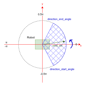
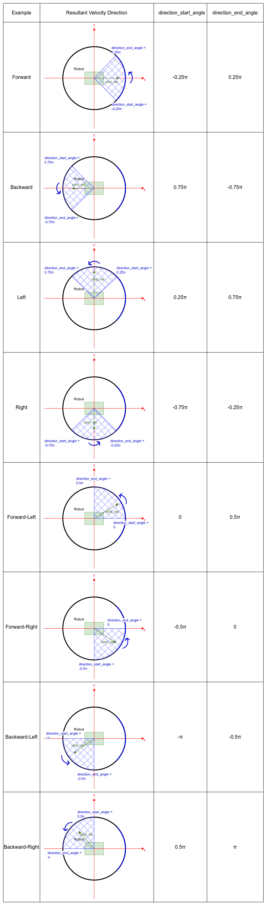
For holomic robots, the holonomic property should be set to true. In this scenario, the linear_min and linear_max parameters should cover the robot’s resultant velocity limits, while the theta_min and theta_max parameters should cover the robot’s angular velocity limits. Additionally, there will be 2 more parameters, direction_start_angle and direction_end_angle, to specify the resultant velocity direction. The covered direction will always span from direction_start_angle to direction_end_angle in the counter-clockwise direction.
Below shows some common configurations for holonomic robots that cover multiple directions of the resultant velocity:
Demo Execution
Once Collision Monitor node has been tuned and cmd_vel topics adjusted, Collision Monitor node is ready to run.
For that, run Nav2 stack as written in Getting Started:
ros2 launch nav2_bringup tb3_simulation_launch.py headless:=False
In parallel console, launch Collision Monitor node by using its launch-file:
ros2 launch nav2_collision_monitor collision_monitor_node.launch.py
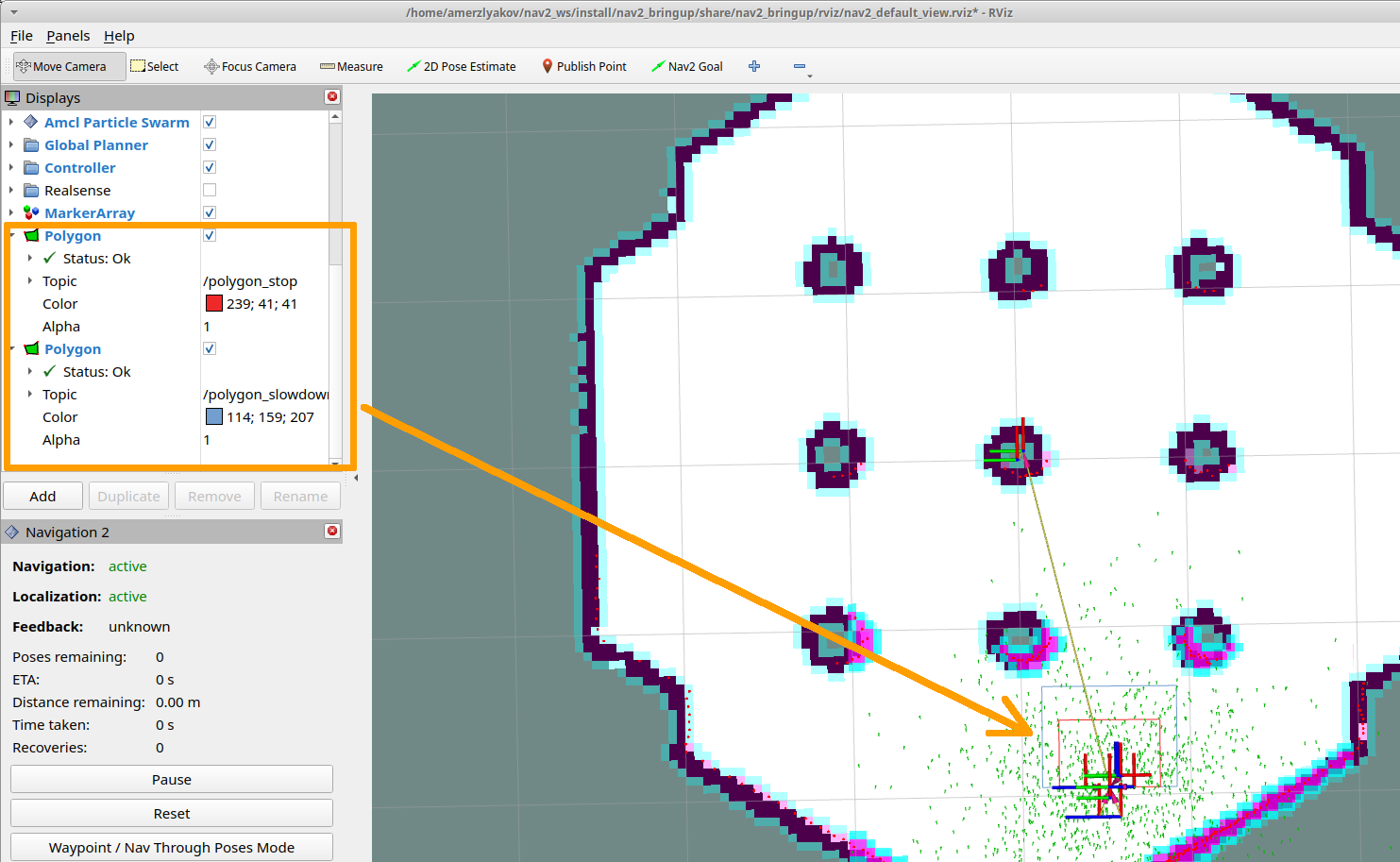
Since both PolygonStop and PolygonSlow polygons will have their own publishers, they could be added to visualization as shown at the picture below:
Set the initial pose and then put Nav2 goal on map. The robot will start its movement, slowing down while running near the obstacles, and stopping in close proximity to them: