Setting Up Transformations
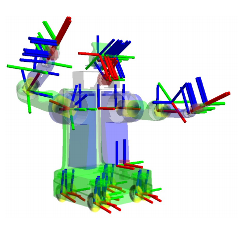
In this guide, we will be looking at the necessary transforms required by Nav2. These transforms allow Nav2 to interpret information coming in from various sources, such as sensors and odometry, by transforming them to the coordinate frames for use. Below is what a full transform tree for a robot looks like but we’ll start with something much more simpler.
For this tutorial, we will first provide a brief introduction to transforms in ROS. Second, we will be working on a simple command-line demo of a TF2 static publisher to see it in action. Lastly, we will outline the necessary transforms that need to be published for Nav2 to function.
Transforms Introduction
Note
This section of this guide has been adapted from the Setting Up You Robot using tf tutorial in the ROS (1) Navigation documentation.
Many ROS packages require the transform tree of a robot to be published using the TF2 ROS package. A transformation tree defines the relations between different coordinate systems, in terms of translation, rotation, and relative motion. To make this more concrete, let us apply an example of a simple robot that has a mobile base with a single laser sensor mounted on top of it.
This robot has two defined coordinate frames: one corresponding to the center point of the mobile base of the robot, and one for the center point of the laser that is mounted on top of the base. We’ll call the coordinate frame attached to the mobile base base_link and we’ll call the coordinate frame attached to the laser base_laser. Note that will be talking more about the naming and conventions of these coordinate frames in the next section.
At this point, let’s assume that we have some data from the laser in the form of distance measurements from the laser’s center point. In other words, we have some data in the base_laser coordinate frame.
Now, suppose we want to take this data and use it to help the mobile base avoid obstacles in the world. To do this successfully, we need a way to transform the laser scan we’ve received from the base_laser frame to the base_link frame. In essence, we need to define a relationship between the base_laser and base_link coordinate frames.
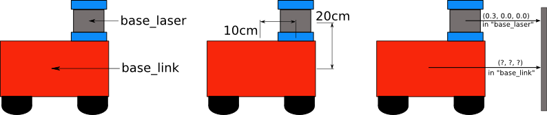
In defining this relationship, let us assume that the only data we have is that the laser is mounted 10cm forward and 20cm above the center point of the mobile base. This gives us a translational offset that relates the base_link frame to the base_laser frame. Specifically, we know that to get data from the base_link frame to the base_laser frame, we must apply a translation of (x: 0.1m, y: 0.0m, z: 0.2m), and transversely, to get data from the base_laser frame to the base_link frame, we must apply the opposite translation (x: -0.1m, y: 0.0m, z: -0.20m).
We could choose to manage this relationship ourselves, meaning to store and apply the appropriate translations between the frames when necessary, but this becomes a real pain as the number of coordinate frames increases. Luckily, we don’t have to do this work ourselves. Instead, we’ll define the relationship between base_link and base_laser once using TF2 and let it manage the transformation between the two coordinate frames for us. This is especially useful when working with non-static transformations, such as a set of frames that are moving relative to each other, like a robot base frame in a map frame.
To define and store the relationship between the base_link and base_laser frames using TF2, we need to add them to a transform tree. Conceptually, each node in the transform tree corresponds to a coordinate frame, and each edge corresponds to the transform that needs to be applied to move from the current node to its child. TF2 uses a tree structure to guarantee that there is only a single traversal that links any two coordinate frames together, and assumes that all edges in the tree are directed from parent to child nodes.
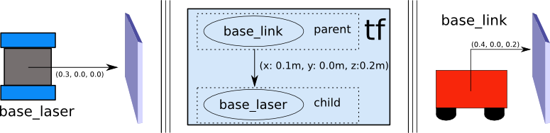
To create a transform tree for our simple example, we’ll create two nodes: one for the base_link coordinate frame and one for the base_laser coordinate frame. To create the edge between them, we first need to decide which node will be the parent and which will be the child. Remember — this distinction is important because TF2 assumes that all transforms move from parent to child.
Let’s choose the base_link coordinate frame as the parent because when other pieces/sensors are added to the robot, it will make the most sense for them to relate to the base_laser frame by traversing through the base_link frame. This means that the transform associated with the edge connecting base_link and base_laser should be (x: 0.1m, y: 0.0m, z: 0.2m).
With this transform tree set up, converting the laser scan received in the base_laser frame to the base_link frame is as simple as making a call to the TF2 library. Our robot can now use this information to reason about laser scans in the base_link frame and safely plan around obstacles in its environment.
Static Transform Publisher Demo
Warning
If you are new to ROS 2 or do not have a working environment yet, then please take some time to properly setup your machine using the resources in the official ROS 2 Installation Documentation
Now let’s try publishing a very simple transform using the static_transform_publisher tool provided by TF2. We will be publishing a transformation from the link base_link to the link base_laser with a translation of (x: 0.1m, y: 0.0m, z: 0.2m). Note that we will be building the transform from the diagram earlier in this tutorial.
Open up your command line and execute the following command:
ros2 run tf2_ros static_transform_publisher 0.1 0 0.2 0 0 0 base_link base_laser
With this, we are now sucessfully publishing our base_link to base_laser transform in TF2. Let us now check if it is working properly through tf2_echo. Open up a separate command line window and execute the following:
ros2 run tf2_ros tf2_echo base_link base_laser
You should be able to observe a repeated output simiar to the one below.
At time 0.0
- Translation: [0.100, 0.000, 0.200]
- Rotation: in Quaternion [0.000, 0.000, 0.000, 1.000]
And that’s it for this short demo - we were able to successfully publish a transform from base_link to base_laser using the TF2 library. Note that we do not recommend using the above demo in publishing transforms for your actual robotics projects, it is just a quick demo to see TF2 in action. For a real robot system, we would create a URDF file which embeds this information and more about your robot for use of the robot_state_publisher rather than the static_transform_publisher. There are more suitable and practical ways to go about this which will be discussed in the Setting Up The URDF tutorial.
See also
If you would like to learn more about TF2 and how to create your own transform publishers, head onto the official TF2 Documentation
Conclusion
In this tutorial, we have discussed about the concept of transforms and how they are used in Nav2.
In the last section, we have also explored using the static_transform_publisher of TF2 to publish our transforms. You may use this to set up your transforms for Nav2, but this is generally not the best way to do it. In most robotics projects, we make use of the Robot State Publisher since it is much easier to use and scales well as our robot gets more complex. We will be talking about the Robot State Publisher, URDF, and how to set it up in the next tutorial on Setting Up The URDF.
Lastly, we also discussed the three published transform requirements of Nav2 and the neccessary REPs to keep in mind when setting them up.