Setting Up Odometry
In this guide, we will be looking at how to integrate our robot’s odometry system with Nav2. First we will provide a brief introduction on odometry, plus the necessary messages and transforms that need to be published for Nav2 to function correctly. Next, we will show how to setup odometry with two different cases. In the first case, we will show how to setup an odometry system for a robot with already available wheel encoders. In the second case, we will build a demo that simulates a functioning odometry system on sam_bot (the robot that we built in the previous section) using Gazebo. Afterwards, we will discuss how various sources of odometry can be fused to provide a smoothed odometry using the robot_localization package. Lastly, we will also show how to publish the odom => base_link transform using robot_localization.
See also
The complete source code in this tutorial can be found in navigation2_tutorials repository under the sam_bot_description package. Note that the repository contains the full code after accomplishing all the tutorials in this guide.
Odometry Introduction
The odometry system provides a locally accurate estimate of a robot’s pose and velocity based on its motion. The odometry information can be obtained from various sources such as IMU, LIDAR, RADAR, VIO, and wheel encoders. One thing to note is that IMUs drift over time while wheel encoders drift over distance traveled, thus they are often used together to counter each other’s negative characteristics.
The odom frame and the transformation associated with it use a robot’s odometry system to publish localization information that is continuous but becomes less accurate over time or distance (depending on the sensor modalities and drift). In spite of this, the information can still be used by the robot to navigate its immediate vicinity (e.g collision avoidance). To obtain consistently accurate odometry information over time, the map frame provides globally accurate information that is used to correct the odom frame.
As discussed in the previous guides and in REP 105, the odom frame is connected to the rest of the system and Nav2 through the odom => base_link transform. This transform is published by a tf2 broadcaster or by frameworks such as robot_localization, which also provide additional functionalities. We will be talking more about robot_localization in a following section.
In addition to the required odom => base_link transform, Nav2 also requires the publishing of nav_msgs/Odometry message because this message provides the velocity information of the robot. In detail, the nav_msgs/Odometry message contains the following information:
# This represents estimates of position and velocity in free space.
# The pose in this message should be specified in the coordinate frame given by header.frame_id
# The twist in this message should be specified in the coordinate frame given by the child_frame_id

# Includes the frame id of the pose parent.
std_msgs/Header header

# Frame id the pose is pointing at. The twist is in this coordinate frame.
string child_frame_id

# Estimated pose that is typically relative to a fixed world frame.
geometry_msgs/PoseWithCovariance pose

# Estimated linear and angular velocity relative to child_frame_id.
geometry_msgs/TwistWithCovariance twist
This message tells us the estimates for the pose and velocity of the robot. The header message provides the timestamped data in a given coordinate frame. The pose message provides the position and orientation of the robot relative to the frame specified in header.frame_id. The twist message gives the linear and angular velocity relative to the frame defined in child_frame_id.
Setting Up Odometry on your Robot
Setting up the odometry system for Nav2 for your physical robot depends a lot on which odometry sensors are available with your robot. Due to the large number of configurations your robot may have, specific setup instructions will not be within the scope of this tutorial. Instead, we will provide some basic examples and useful resources to help you configure your robot for Nav2.
To start, we will use an example of a robot with wheel encoders as its odometry source. Note that wheel encoders are not required for Nav2 but it is common in most setups. The goal in setting up the odometry is to compute the odometry information and publish the nav_msgs/Odometry message and odom => base_link transform over ROS 2. To calculate this information, you will need to setup some code that will translate wheel encoder information into odometry information, similar to the snippet below:
linear = (right_wheel_est_vel + left_wheel_est_vel) / 2
angular = (right_wheel_est_vel - left_wheel_est_vel) / wheel_separation;
The right_wheel_est_vel and left_wheel_est_vel are the estimated velocities of the right and left wheels respectively, and the wheel separation is the distance between the wheels. The values of right_wheel_est_vel and left_wheel_est_vel can be obtained by simply getting the changes in the positions of the wheel joints over time. This information can then be used to publish the Nav2 requirements. A basic example on how to do this can be found in the Navigation documentation on odometry located here
An alternative to manually publishing this information that we recommend is through the ros2_control framework. The ros2_control framework contains various packages for real-time control of robots in ROS 2. For wheel encoders, ros2_control has a diff_drive_controller (differential drive controller) under the ros2_controller package. The diff_drive_controller takes in the geometry_msgs/Twist messages published on cmd_vel topic, computes odometry information, and publishes nav_msgs/Odometry messages on odom topic. Other packages that deal with different kind of sensors are also available in ros2_control.
See also
For more information, see the ros2_control documentation and the Github repository of diff_drive_controller.
For other types of sensors such as IMU, VIO, etc, their respective ROS drivers should have documentation on how publish the odometry information. Keep in mind that Nav2 requires the nav_msgs/Odometry message and odom => base_link transforms to be published and this should be your goal when setting up your odometry system.
Simulating an Odometry System using Gazebo
In this section, we will be using Gazebo to simulate the odometry system of sam_bot, the robot that we built in the previous section of this tutorial series. You may go through that guide first or grab the complete source here.
Note
If you are working on your own physical robot and have already set up your odometry sensors, you may opt to skip this section and head onto the next one where we fuse IMU and odometry messages to provide a smooth odom => base_link transformation.
As an overview for this section, we will first setup Gazebo and the necessary packages required to make it work with ROS 2. Next, we will be adding Gazebo plugins, which simulate an IMU sensor and a differential drive odometry system, in order to publish sensor_msgs/Imu and nav_msgs/Odometry messages respectively. Lastly, we will spawn sam_bot in a Gazebo environment and verify the published sensor_msgs/Imu and nav_msgs/Odometry messages over ROS 2.
Setup and Prerequisites
Gazebo is a 3D simulator that allows us to observe how our virtual robot will function in a simulated environment. To start using Gazebo with ROS 2, follow the installation instructions in the Gazebo Installation Documentation.
We also need to install the gazebo_ros_pkgs package to simulate odometry and control the robot with ROS 2 in Gazebo:
sudo apt install ros-<ros2-distro>-gazebo-ros-pkgs
You can test if you have successfully set up your ROS 2 and Gazebo environments by following the instructions given here.
Note that we described sam_bot using URDF. However, Gazebo uses Simulation Description Format (SDF) to describe a robot in its simulated environment. Fortunately, Gazebo automatically translates compatible URDF files into SDF. The main requirement for the URDF to be compatible with Gazebo is to have an <inertia> element within each <link> element. This requirement is already satisfied in the URDF file of sam_bot, so it can already be used in Gazebo.
See also
For more information on how to use URDF in Gazebo, see Tutorial: Using a URDF in Gazebo.
Adding Gazebo Plugins to a URDF
We will now add the IMU sensor and the differential drive plugins of Gazebo to our URDF. For an overview of the different plugins available in Gazebo, have a look at Tutorial: Using Gazebo plugins with ROS.
For our robot, we will be using the GazeboRosImuSensor which is a SensorPlugin. A SensorPlugin must be attached to a link, thus we will create an imu_link to which the IMU sensor will be attached. This link will be referenced under the <gazebo> element. Next, we will set /demo/imu as the topic to which the IMU will be publishing its information, and we will comply with REP145 by setting initalOrientationAsReference to false. We will also add some noise to the sensor configuration using Gazebo’s sensor noise model.
Now, we will set up our IMU sensor plugin according to the description above by adding the following lines before the </robot> line in our URDF:
132 133 134 135 136 137 138 139 140 141 142 143 144 145 146 147 148 149 150 151 152 153 154 155 156 157 158 159 160 161 162 163 164 165 166 167 168 169 170 171 172 173 174 175 176 177 178 179 180 181 182 183 184 185 186 187 188 189 190 191 192 193 194 195 196 197 198 199 200 201 202 203 204 205 206 207 208 209 210 211 212 213 214 215 216 217 218 219 220 221 | <link name="imu_link"> <visual> <geometry> <box size="0.1 0.1 0.1"/> </geometry> </visual> <collision> <geometry> <box size="0.1 0.1 0.1"/> </geometry> </collision> <xacro:box_inertia m="0.1" w="0.1" d="0.1" h="0.1"/> </link> <joint name="imu_joint" type="fixed"> <parent link="base_link"/> <child link="imu_link"/> <origin xyz="0 0 0.01"/> </joint> <gazebo reference="imu_link"> <sensor name="imu_sensor" type="imu"> <plugin filename="libgazebo_ros_imu_sensor.so" name="imu_plugin"> <ros> <namespace>/demo</namespace> <remapping>~/out:=imu</remapping> </ros> <initial_orientation_as_reference>false</initial_orientation_as_reference> </plugin> <always_on>true</always_on> <update_rate>100</update_rate> <visualize>true</visualize> <imu> <angular_velocity> <x> <noise type="gaussian"> <mean>0.0</mean> <stddev>2e-4</stddev> <bias_mean>0.0000075</bias_mean> <bias_stddev>0.0000008</bias_stddev> </noise> </x> <y> <noise type="gaussian"> <mean>0.0</mean> <stddev>2e-4</stddev> <bias_mean>0.0000075</bias_mean> <bias_stddev>0.0000008</bias_stddev> </noise> </y> <z> <noise type="gaussian"> <mean>0.0</mean> <stddev>2e-4</stddev> <bias_mean>0.0000075</bias_mean> <bias_stddev>0.0000008</bias_stddev> </noise> </z> </angular_velocity> <linear_acceleration> <x> <noise type="gaussian"> <mean>0.0</mean> <stddev>1.7e-2</stddev> <bias_mean>0.1</bias_mean> <bias_stddev>0.001</bias_stddev> </noise> </x> <y> <noise type="gaussian"> <mean>0.0</mean> <stddev>1.7e-2</stddev> <bias_mean>0.1</bias_mean> <bias_stddev>0.001</bias_stddev> </noise> </y> <z> <noise type="gaussian"> <mean>0.0</mean> <stddev>1.7e-2</stddev> <bias_mean>0.1</bias_mean> <bias_stddev>0.001</bias_stddev> </noise> </z> </linear_acceleration> </imu> </sensor> </gazebo> |
Now, let us add the differential drive ModelPlugin. We will configure the plugin such that nav_msgs/Odometry messages are published on the /demo/odom topic. The joints of the left and right wheels will be set to the wheel joints of sam_bot. The wheel separation and wheel diameter are set according to the values of the defined values of wheel_ygap and wheel_radius respectively.
To include this plugin in our URDF, add the following lines after the </gazebo> tag of the IMU plugin:
223 224 225 226 227 228 229 230 231 232 233 234 235 236 237 238 239 240 241 242 243 244 245 246 247 248 249 | <gazebo> <plugin name='diff_drive' filename='libgazebo_ros_diff_drive.so'> <ros> <namespace>/demo</namespace> </ros> <!-- wheels --> <left_joint>drivewhl_l_joint</left_joint> <right_joint>drivewhl_r_joint</right_joint> <!-- kinematics --> <wheel_separation>0.4</wheel_separation> <wheel_diameter>0.2</wheel_diameter> <!-- limits --> <max_wheel_torque>20</max_wheel_torque> <max_wheel_acceleration>1.0</max_wheel_acceleration> <!-- output --> <publish_odom>true</publish_odom> <publish_odom_tf>false</publish_odom_tf> <publish_wheel_tf>true</publish_wheel_tf> <odometry_frame>odom</odometry_frame> <robot_base_frame>base_link</robot_base_frame> </plugin> </gazebo> |
Launch and Build Files
We will now edit our launch file, launch/display.launch.py, to spawn sam_bot in Gazebo. Since we will be simulating our robot, we can remove the GUI for the joint state publisher by deleting the following lines inside the generate_launch_description():
joint_state_publisher_gui_node = launch_ros.actions.Node(
  package='joint_state_publisher_gui',
  executable='joint_state_publisher_gui',
  name='joint_state_publisher_gui',
  condition=launch.conditions.IfCondition(LaunchConfiguration('gui'))
)
Remove the following gui param:
DeclareLaunchArgument(name='gui', default_value='True',
                      description='Flag to enable joint_state_publisher_gui')
Remove the condition from the joint_state_publisher_node:
joint_state_publisher_node = launch_ros.actions.Node(
  package='joint_state_publisher',
  executable='joint_state_publisher',
  name='joint_state_publisher',
  arguments=[default_model_path],
  condition=launch.conditions.UnlessCondition(LaunchConfiguration('gui')) # Remove this line
)
Next, open package.xml and delete the line:
<exec_depend>joint_state_publisher_gui</exec_depend>
To launch Gazebo, add the following before the joint_state_publisher_node, line in display.launch.py
launch.actions.ExecuteProcess(cmd=['gazebo', '--verbose', '-s', 'libgazebo_ros_init.so', '-s', 'libgazebo_ros_factory.so'], output='screen'),
We will now add a node that spawns sam_bot in Gazebo. Open launch/display.launch.py again and paste the following lines before the return launch.LaunchDescription([ line.
spawn_entity = launch_ros.actions.Node(
  package='gazebo_ros',
  executable='spawn_entity.py',
  arguments=['-entity', 'sam_bot', '-topic', 'robot_description'],
  output='screen'
)
Then add the line spawn_entity, before the rviz_node line, as shown below.
      robot_state_publisher_node,
      spawn_entity,
      rviz_node
])
Build, Run and Verification
Let us run our package to check if the /demo/imu and /demo/odom topics are active in the system.
Navigate to the root of the project and execute the following lines:
colcon build
. install/setup.bash
ros2 launch sam_bot_description display.launch.py
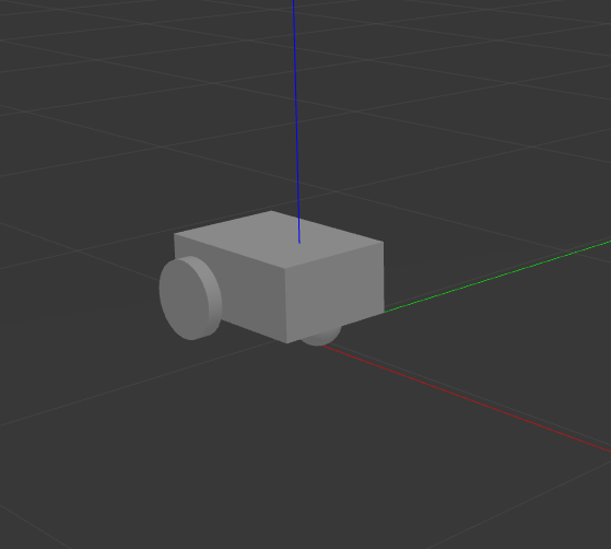
Gazebo should launch and you should see a 3D model of sam_bot:
To see the active topics in the system, open a new terminal and execute:
ros2 topic list
You should see /demo/imu and /demo/odom in the list of topics.
To see more information about the topics, execute:
ros2 topic info /demo/imu
ros2 topic info /demo/odom
You should see an output similar to below:
Type: sensor_msgs/msg/Imu
Publisher count: 1
Subscription count: 0
Type: nav_msgs/msg/Odometry
Publisher count: 1
Subscription count: 0
Observe that the /demo/imu topic publishes sensor_msgs/Imu type messages while the /demo/odom topic publishes nav_msgs/Odometry type messages. The information being published on these topics come from the gazebo simulation of the IMU sensor and the differential drive respectively. Also note that both topics currently have no subscribers. In the next section, we will create a robot_localization node that will subscribe to these two topics. It will then use the messages published on both topics to provide a fused, locally accurate and smooth odometry information for Nav2.
Robot Localization Demo
The robot_localization package is used to provide a fused and locally accurate smooth odometry information from the data provided by N odometry sensor inputs. These information can be provided to the package through nav_msgs/Odometry, sensor_msgs/Imu, geometry_msgs/PoseWithCovarianceStamped, and geometry_msgs/TwistWithCovarianceStamped messages.
A usual robot setup consists of at least the wheel encoders and IMU as its odometry sensor sources. When multiple sources are provided to robot_localization, it is able to fuse the odometry information given by the sensors through the use of state estimation nodes. These nodes make use of either an Extended Kalman filter (ekf_node) or an Unscented Kalman Filter (ukf_node) to implement this fusion. In addition, the package also implements a navsat_transform_node which transforms geographic coordinates into the robot’s world frame when working with GPS.
Fused sensor data is published by the robot_localization package through the odometry/filtered and the accel/filtered topics, if enabled in its configuration. In addition, it can also publish the odom => base_link transform on the /tf topic.
See also
More details on robot_localization can be found in the official Robot Localization Documentation.
If your robot is only able to provide one odometry source, the use of robot_localization would have minimal effects aside from smoothing. In this case, an alternative approach is to publish transforms through a tf2 broadcaster in your single source of odometry node. Nevertheless, you can still opt to use robot_localization to publish the transforms and some smoothing properties may still be observed in the output.
See also
For more information on how to write a tf2 broadcaster, you can check Writing a tf2 broadcaster (C++) (Python).
For the rest of this section, we will show how to use robot_localization to fuse the sensors of sam_bot. It will use the sensor_msgs/Imu messages published on /demo/Imu and the nav_msgs/Odometry message published on /demo/odom and then it will publish data on odometry/filtered, accel/filtered, and /tf topics.
Configuring Robot Localization
Let us now configure the robot_localization package to use an Extended Kalman Filter (ekf_node) to fuse odometry information and publish the odom => base_link transform.
First, install the robot_localization package using your machines package manager or by executing the following command:
sudo apt install ros-<ros2-distro>-robot-localization
Next, we specify the parameters of the ekf_node using a YAML file. Create a directory named config at the root of your project and create a file named ekf.yaml. Copy the following lines of code into your ekf.yaml file.
### ekf config file ###
ekf_filter_node:
    ros__parameters:
# The frequency, in Hz, at which the filter will output a position estimate. Note that the filter will not begin
# computation until it receives at least one message from one of theinputs. It will then run continuously at the
# frequency specified here, regardless of whether it receives more measurements. Defaults to 30 if unspecified.
        frequency: 30.0

# ekf_localization_node and ukf_localization_node both use a 3D omnidirectional motion model. If this parameter is
# set to true, no 3D information will be used in your state estimate. Use this if you are operating in a planar
# environment and want to ignore the effect of small variations in the ground plane that might otherwise be detected
# by, for example, an IMU. Defaults to false if unspecified.
        two_d_mode: false

# Whether to publish the acceleration state. Defaults to false if unspecified.
        publish_acceleration: true

# Whether to broadcast the transformation over the /tf topic. Defaultsto true if unspecified.
        publish_tf: true

# 1. Set the map_frame, odom_frame, and base_link frames to the appropriate frame names for your system.
#     1a. If your system does not have a map_frame, just remove it, and make sure "world_frame" is set to the value of odom_frame.
# 2. If you are fusing continuous position data such as wheel encoder odometry, visual odometry, or IMU data, set "world_frame"
#    to your odom_frame value. This is the default behavior for robot_localization's state estimation nodes.
# 3. If you are fusing global absolute position data that is subject to discrete jumps (e.g., GPS or position updates from landmark
#    observations) then:
#     3a. Set your "world_frame" to your map_frame value
#     3b. MAKE SURE something else is generating the odom->base_link transform. Note that this can even be another state estimation node
#         from robot_localization! However, that instance should *not* fuse the global data.
        map_frame: map              # Defaults to "map" if unspecified
        odom_frame: odom            # Defaults to "odom" if unspecified
        base_link_frame: base_link  # Defaults to "base_link" ifunspecified
        world_frame: odom           # Defaults to the value ofodom_frame if unspecified

        odom0: demo/odom
        odom0_config: [true,  true,  true,
                       false, false, false,
                       false, false, false,
                       false, false, true,
                       false, false, false]

        imu0: demo/imu
        imu0_config: [false, false, false,
                      true,  true,  true,
                      false, false, false,
                      false, false, false,
                      false, false, false]
In this configuration, we defined the parameter values of frequency, two_d_mode, publish_acceleration, publish_tf, map_frame, odom_frame, base_link_frame, and world_frame. For more information on the other parameters you can modify, see Parameters of state estimation nodes, and a sample efk.yaml can be found here.
To add a sensor input to the ekf_filter_node, add the next number in the sequence to its base name (odom, imu, pose, twist). In our case, we have one nav_msgs/Odometry and one sensor_msgs/Imu as inputs to the filter, thus we use odom0 and imu0. We set the value of odom0 to demo/odom, which is the topic that publishes the nav_msgs/Odometry. Similarly, we set the value of imu0 to the topic that publishes sensor_msgs/Imu, which is demo/imu.
You can specify which values from a sensor are to be used by the filter using the _config parameter. The order of the values of this parameter is x, y, z, roll, pitch, yaw, vx, vy, vz, vroll, vpitch, vyaw, ax, ay, az. In our example, we set everything in odom0_config to false except the 1st, 2nd, 3rd, and 12th entries, which means the filter will only use the x, y, z, and the vyaw values of odom0.
In the imu0_config matrix, you’ll notice that only roll, pitch, and yaw are used. Typical mobile robot-grade IMUs will also provide angular velocities and linear accelerations. For robot_localization to work properly, you should not fuse in multiple fields that are derivative of each other. Since angular velocity is fused internally to the IMU to provide the roll, pitch and yaw estimates, we should not fuse in the angular velocities used to derive that information. We also do not fuse in angular velocity due to the noisy characteristics it has when not using exceptionally high quality (and expensive) IMUs.
See also
For more advise on configuration of input data to robot_localization, see Preparing Your Data for Use with robot_localization, and Configuring robot_localization.
Launch and Build Files
Now, let us add the ekf_node into the launch file. Open launch/display.launch.py and paste the following lines before the return launch.LaunchDescription([ line.
robot_localization_node = launch_ros.actions.Node(
       package='robot_localization',
       executable='ekf_node',
       name='ekf_filter_node',
       output='screen',
       parameters=[os.path.join(pkg_share, 'config/ekf.yaml'), {'use_sim_time': LaunchConfiguration('use_sim_time')}]
)
Next, add the following launch arguments within the return launch.LaunchDescription([ block.
launch.actions.DeclareLaunchArgument(name='use_sim_time', default_value='True',
                                            description='Flag to enable use_sim_time'),
Lastly, add robot_localization_node, above the rviz_node line to launch the robot localization node.
      robot_state_publisher_node,
      spawn_entity,
      robot_localization_node,
      rviz_node
])
Next, we need to add the robot_localization dependency to our package definition. Open package.xml and add the following line below the last <exec_depend> tag.
<exec_depend>robot_localization</exec_depend>
Lastly, open CMakeLists.txt and append the config directory inside the install(DIRECTORY...), as shown in the snippet below.
install(
  DIRECTORY src launch rviz config
  DESTINATION share/${PROJECT_NAME}
)
Build, Run and Verification
Let us now build and run our package. Navigate to the root of the project and execute the following lines:
colcon build
. install/setup.bash
ros2 launch sam_bot_description display.launch.py
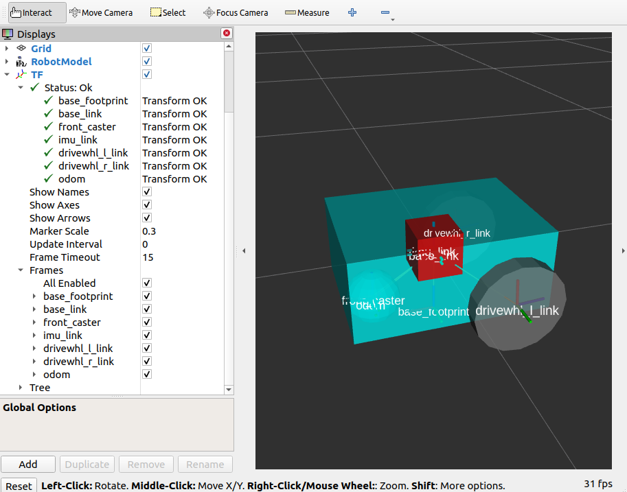
Gazebo and RVIZ should launch. In the RVIZ window, you should see the model and TF frames of sam_bot:
Next, let us verify that the odometry/filtered, accel/filtered, and /tf topics are active in the system. Open a new terminal and execute:
ros2 topic list
You should see odometry/filtered, accel/filtered, and /tf in the list of the topics.
You can also check the subscriber count of these topics again by executing:
ros2 topic info /demo/imu
ros2 topic info /demo/odom
You should see that /demo/imu and /demo/odom now both have 1 subscriber each.
To verify that the ekf_filter_node are the subscribers of these topics, execute:
ros2 node info /ekf_filter_node
You should see an output as shown below.
/ekf_filter_node
Subscribers:
  /demo/imu: sensor_msgs/msg/Imu
  /demo/odom: nav_msgs/msg/Odometry
  /parameter_events: rcl_interfaces/msg/ParameterEvent
  /set_pose: geometry_msgs/msg/PoseWithCovarianceStamped
Publishers:
  /accel/filtered: geometry_msgs/msg/AccelWithCovarianceStamped
  /diagnostics: diagnostic_msgs/msg/DiagnosticArray
  /odometry/filtered: nav_msgs/msg/Odometry
  /parameter_events: rcl_interfaces/msg/ParameterEvent
  /rosout: rcl_interfaces/msg/Log
  /tf: tf2_msgs/msg/TFMessage
Service Servers:
   ...
From the output above, we can see that the ekf_filter_node is subscribed to /demo/imu and /demo/odom. We can also see that the ekf_filter_node publishes on the odometry/filtered, accel/filtered, and /tf topics.
You may also verify that robot_localization is publishing the odom => base_link transform by using the tf2_echo utility. Run the folllowing command in a separate command line terminal:
ros2 run tf2_ros tf2_echo odom base_link
You should see a continuous output similar to what is shown below.
At time 8.842000000
- Translation: [0.003, -0.000, 0.127]
- Rotation: in Quaternion [-0.000, 0.092, 0.003, 0.996]
At time 9.842000000
- Translation: [0.002, -0.000, 0.127]
- Rotation: in Quaternion [-0.000, 0.092, 0.003, 0.996]
Conclusion
In this guide, we have discussed the messages and transforms that are expected by Nav2 from the odometry system. We have seen how to set up an odometry system and how to verify the published messages. We also have discussed how multiple odometry sensors can be used to provide a filtered and smoothed odometry using robot_localization. We have also checked if the odom => base_link transform is being published correctly by robot_localization.